-
Analog contacts
-
The purpose of the lecture: The role of the Ford programming cycle, the purpose of analog contacts, ADC and PWM.
The content of the lecture:
3.1. The for cycle. Increment. Decrement
3.2. Analog input. ADC.
3.3. Analog output. PWM signal.
Didactic units: for loop, increment, decrement, analog input, analog output, pulse width modulation, analog digital converter.
3.1. The for loop. Increment. Decrement
A loop is used to perform multiple runs of the same executable program code. The loop is executed repeatedly until some task condition is met. If the condition is met, the loop stops executing and the program itself produces a certain result.
Iteration in programming is the repetition of an action.Запомнить!
for (начала цикла; условие; итерация цикла)
{код выполняемой программы}
Increment is an operation in programming languages that increments a variable by one. It is defined by the expression i = i + 1. In the for loop, the increment is briefly written i++. Let's give an example.Пример 3.1. Инкремент
i=i+1=0+1=1, при i = 0 i=i+1=1+1=2 i=i+1=2+1=3 i=i+1=3+1=4
i=i+1=4+1=5
Decrement is an operation that, on the contrary, reduces a variable by one. It is defined by the expression i=i–1. In the for loop, the decrement is briefly written i--. Let's give an example.
Now let's give a specific example related to the for loop. Let's set the iteration of the loop to 5, i.e. we output the values of the digits from 1 to 5 to the column only once.Пример 3.2. Инкремент
i=i+1=10-1=9, при i = 10 i=i+1=9-1=8
i=i+1=8-1=7 i=i+1=7-1=6
i=i+1=6-1=5
To do this, use the void setup() function.
Листинг 3.1. Цикл for
void setup(){

The result of the program is shown in Figure 3.1. This program works as follows. The report starts at a=0 with an addition of one with each iteration. As a result, after adding each unit, a message is displayed in the Serial.println(a) column.The loop is executed until condition a<6 is met. In this case, when the value 6 is reached, the cycle is interrupted.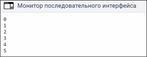
P. 3.1. The result of the output of the decrement using the for loop
3.1. Analog input. ADC
There are only five analog ports in the Arduino Uno: A1, A2, A3, A4 and A5. It should be noted that by default all ports are configured as inputs. The analog port can receive an analog voltage signal. In the truest sense of the word, the analog port can "measure" voltage from 0 to 5V. The analog voltage is digitized using an analog digital converter, briefly called an ADC. The ADC has a bit depth of 10 bits, which is 210 = 1024 digital values. It turns out if a voltage of 5V is applied to the analog port, i.e. the maximum value, then using the ADC, the voltage is converted to a value of 1024. Let's conduct an experiment.Experiment 3.1. Analog input. Output of digital values. Required components: Arduino Uno - 1 pc. Breadboard - 1 pc. Potentiometer - 1 pc.
The task of this experiment is to display digital values from 0... 1023 on the monitor, which corresponds to a voltage from 0 ... 5V. That is, we will check the operability of the analog ports. The 5V power supply will supply the Arduino board itself using a USB port, but it has nothing to do with its microcontroller. By connecting to the positive terminal +U In the potentiometer, we connect a 5V power supply. The second terminal is grounded to GND. We connect the middle terminal to any analog port. In our case, the analog port is A0. Having connected everything as shown in Figure 3.2, we will write the program code (Listing 3.2).
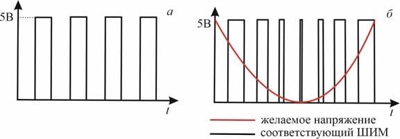
Figure 3.2. Analog signal output to the monitor
Листинг3.2. Функция analogRead(). АЦП. Потенциометр.
intpot= 0; // Аналоговый вход потенциометра.
intval;// переменная для хранения значения с потен-ра. voidsetup() { pinMode(pot,INPUT);
Serial.begin(9600);
}
void loop(){
val=analogRead(pot); // считать показания с потен-ра. Serial.println(val);
delay(300);}
In this program, we assign the name pot with the value 0 to the variable, i.e. we use an analog zero contact. Next, we set the data transfer rate of 9600 bps once and output the analogRead(pin) to the screen to be read. As noted above, the void loop() function is a continuous, cyclic function, so you need to set the shutter speed between the lines to 300 milliseconds. This is done using the delay(300) command.
3.1. Analog output. PWM signal
An analog output is understood as the output of voltage from a microcontroller in the form of a discrete value signal (divided, intermittent), i.e. they can output either a voltage of 5V or ground 0V. This alternation of the voltage signal is called pulse width modulation (PWM signal).
3.3. PWM signal (a); Comparison of the PWM signal with the analog signal (b).
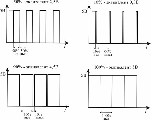
A PWM signal is a pulse emitted in a short period of time (Fig.3.3, a). This signal can be visually compared with the voltage of the analog signal by the pulse width. The smaller the pulse width, i.e., the shorter its duration, the less the voltage itself at the output of the contact will be emitted as a result (Fig.3.3, b). If we want to get the maximum voltage, then for this we must strive to increase the pulse width, i.e. increase the duration of the oscillation. The ratio of the duration of the oscillation of one pulse to its period is called the duty cycle. The higher the duty cycle of the PWM signal, the higher the voltageemits. Let's give an example (Fig.3.4).
Contacts that can work as analog outputs are located at the top of the Arduino Uno board and are marked with the symbol "tilde" (~). Digital contacts D3, D5, D6, D9, D10 and D11 with a tilde can emit a PWM signal. To do this, use the analogWrite() function. Here is an example with the same flashing LED. Instead of digitalWrite(), you can use a PWM signal with analogWrite() voltage supply function. By making the appropriate contact with the pinMode output mode(3,OUTPUT), we get a similar flashing LED (Listing 3.3).
Листинг 3.3.Функция analogWrite(). ШИМ сигнал.
void setup(){ pinMode(3,OUTPUT);
}
voidloop(){ analoWrite(3,HIGH); delay(1000); analogWrite(3,LOW); delay(1000);
}
Attention! When using the analogWrite() function, the connection is made to a PWM-enabled contact. On the board, in some contacts, it is indicated by the tilde sign (~). -
Открыто с: понедельник, 6 октября 2025, 00:00Срок сдачи: понедельник, 13 октября 2025, 00:00
-