-
Introduction to Arduino
-
Purpose of the lecture: Introduction to programming and introduction to the general structure of the ArduinoUno board.
1.1.
Introduction to C++ programming.
1.1.1.
Syntax.
1.1.2.
Identifier.
1.1.3.
Setup () and loop () functions.
1.1.4.
pinMode().
1.2.
Arduino family boards.
1.2.1.
ArduinoUno board.
1.2.2.
Male connectors.
1.2.3.
Digital contacts.
1.2.4.
Analog contacts.
1.2.5.
Power supply contacts.
1.2.6.
USB connector.
1.2.7.
External power connector.
1.2.8.
LED indicators.
1.2.9.
Reset button.
Didactic units: identifier, ArduinoUno, digital ticks, analog contacts, comments.
Introduction to C++ Programming
The entire syntax used for the operation of automation and ro-bototechnics, in particular, the C/C + + language is used on the Arduino board. Before connecting various microcircuits and electronic components to the Arduino board, you must first familiarize yourself with the basics of programming in order to set various commands to perform a particular task.
1.1.1. Syntax
As you already know, the term syntax is a section of the science of language that studies phrases and sentences. In our case, the syntax of the language in programming also has its own supposedly specially written language, designed to perform various functions in the field of information technology, mechanized devices operating under pre-data programs. The syntax of the C/C + + language in one word is a specially built, correctly thought out grammar of the language, capable of re-giving, reading and even writing various commands in the machine code language.
Comments/* */and//
Comments are lines in a program that are used to form yourself or others about how the program works. They are ig-normed by the compiler and are not exported to the processor, so they do not take up space in the microcontroller memory. Comments are intended only to help you understand (or remember) how your program works or explain it to others. There are two ways to mark a line as a comment :/* */and//.
In the first method, the comment is multiline, i.e., for example, a whole paragraph can be commented (example 1.1).
Example 1.1. Comments/* */
/*
comment text
*/
If you want to comment on one line, then for this you need to place double inclined sticks of the form//next to the code (on one line). In this case, after//, the compiler completely ignores the written text (example 1.2).
Example 1.2. Comments//
//comment text
Semicolon;
Semicolon - used to indicate the end of the action of the operator (example 1.3).
Example 1.3. Semicolon
int a=4;
Note: A semicolon forgotten at the end of a line results in a compilation error. If the compiler issues an error, one of the first steps should be to check for missing semicolons, in the code immediately preceding the line in which the compiler issued the warning. Фигурные скобки {}
Braces {} are used to wrap the action of some inbound code inside these brackets. Such brackets are used in various functions, classes, condition, cycle, etc. Here are some examples:
Braces in the body of the function. If you want to declare some function, then this function will not function without curly braces, even if it is empty. Any program code after the function declaration is placed inside curly braces. It is also called specifying the program code in the body of the function (example 1.4).
Example 1.4. Curly braces in the function body
voidsetup()
{…}// тело функции
b) Braces in conditional statements. In the C/C + + language, to write a task execution condition, the algorithm of the task being performed is placed in the first curly bracket depending on the task condition, if the condition in parentheses is not fulfilled, then the command is executed in the second curly bracket. (Example 1.5).
Example 1.5. Curly braces in a conditional operatorif
if (…)
{…}
else {…}
c) Braces in a loop. In the for loop, places the executed program code inside the curly braces, depending on the condition of the task included in the parentheses (example 1.6).
Example 1.6. Curly braces in the for loop
for(…)
{…}
d) Braces in while and dowhile. In both cases, the executed commands are placed in curly brackets, and the conditions for executing these commands are placed in parentheses (example 1.7).
Example 1.7. Curly braces in a loophile and before...while
while(…)
{…}
do{…}
while(…)
1.1.1. Identifier
Names used for variables, functions, labels, and other user-defined objects are called identifiers. Identification designates an "identifier" - a unique feature of an object that allows you to distinguish it from other objects, that is, to identify it. Let's explain a small program given in example 1.8.
Example 1.8. ID
intcount = 3;
intteat123 = 9;
intboot;
voidsetup(){
Serial.begin(9600);
boot = count + teat123;
Serial.println(c);
}
void loop(){
}
Three independent changes have been announced: count, test123 and boots with the first two values of 3 and 9. It should be noted that the ID is from and gives an error in the entries of uppercase, uppercase and lowercase letters if they differ. In our case, if we write the formula for adding two values of variables in capital letters: boot = Count + Teat123 then, of course, the identifier cannot recognize them, since they differ from previously declared variables and the compiler will not let them in, while it will give the corresponding error. To eliminate this error, you need to identify these variables, as previously declared by boot, counteat123, and then perform the addition operation and give the appropriate result.
Функцийsetup() иloop()
The setup () function is called when the program starts. Used to initialize variables, determine output modes, start-up libraries used, etc. The setup () function starts only once, after each power-up or reset of the Arduino board.
Example 1.7. setup() function
void setup(){
Serial.begin(9600);
Serial.println("Hello, ATT");
void loop(){
}
As shown in Example 1.7. in the body of the voidsetup () function, the crazed message output co-manda Serial.println ("Hello, ATT") displays the message only once. Since the function itself, as noted above, is completed once. The result of message output is shown in Fig. 1.1.
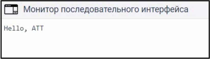
Рис. 1.1. Результат работы функции setup()
In the voidloop () function, the command is executed cyclically, i.e. multi-rate. Let's give the same example with the output of a message through a monitor after an authoritative interface. To do this, let's write a program (example 1.8).
Пример 1.8. Функция loop()
void setup(){
Serial.begin(9600);
void loop(){
Serial.println("Hello, ATT");
delay(500);
}
The result of the program is shown in Figure 1.2. That is, the essence of this program is to repeatedly display the message from a new and new line using the Seri-al.println ("Hello, ATT") command with a delay interval between lines of 500 milliseconds.
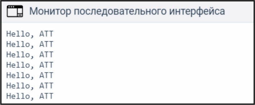
Рис. 1.2. Результат работы функции loop()
1.1.1. pinMode()
The pinMode () function is used to set the operating mode of the ports. It is declared in the body of the voidsetup () function and executed once.
Запомнить!
pinMode(pin, mode)
pin– номер входа или выхода порта, которому мы можем установить; mode – режим работы порта, например, INPUTили OUTPUT.
The program code with LED connection is shown in example 1.9. In order for the LED to light up, it is necessary to connect it to digital port number 8 and set it with the voltage output mode.
Пример 1.9. pinMode()
void setup(){
Serial.begin(9600);
pinMode(8, OUTPUT);// Установили порт 8 с режимом
// вывода
void loop(){
digitalWrite(8, HIGH);
}
1.2. Arduino family board
The Arduino family board is very diverse in size, specifications and purpose. Ониделятсяна ArduinoUno, ArduinoLe-onardo, ArduinoDue, ArduinoYUN, ArduinoTRE, ArduinoMicro, ArduinoRobot, ArduinoEsplora, ArduinoMegaADK, ArduinoEthernet, ArduinoMega 2560, Ardu-inoMini, LilyPadArduinoUSB, LilyPadArduinoSimple, LilyPadArduinoSimple-Snap, LilyPadArduino, ArduinoNano, ArduinoProMini, ArduinoProи ArduinoFio. All of them differ from each other in the number of digital and analog inputs/outputs, microcontroller brands, Flash memory, frequencies, etc. In our case, in all lessons on the basics of robotics, we will use the ArduinoUno board with a built-in ATmega328 microcontroller.
1.1.2. ArduinoUno board
The most popular Arduino board currently in existence is the Arduino Uno. It has a number of functions that make it universal. ArduinoUno consists of a microcontroller of the ATmega328 brand, analog and digital ports, LED indicators, an overload button, a USB port, a power connector (Fig. 1.3).
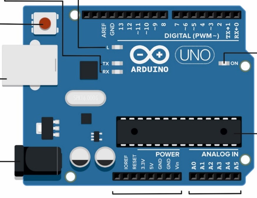
Рис.1.3. Плата Arduino Uno
As a controller, a ATmega328 microprocessor is built into it, which can receive power directly from a USB, battery or network adapter. This board operates at a voltage of 5 V. The board also contains 14 digital I/O contacts, six of which can be used as pulse width modulation (PWM) outputs. In addition, it has six analog inputs plus RX/TX pins (serial data). Installed memory - 32 KB of Flash memory, 2 KB of static RAM (SRAM) and 1 KB of electrically erasable programmable read-only memory.
Microcontroller ATmega328. This integrated circuit (or IC) is the "brain" of the board and provides its computing power. Different Arduino models use different versions of the microcontroller. The Arduino Uno board is based on the Atmel ATmega328 microcontroller. In fact, this is a small computer that can make decisions on its own. On a software board, it is a controller that executes commands that include several different types of memory that store data and commands. Microcontrollers also support several different ways of sending and receiving data (Fig. 1.4).
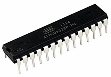
Рис. 1.4. Микроконтроллер
1.1.2. Male connectors
The microcontroller is connected to a series of connectors known as pin connectors or pins. They are located next to the top and bottom edges of the board. There are three types of contacts: digital, analog and power. The pins are needed to supply power to the Arduino board, as well as to be able to quickly and easily connect additional components to the board, such as layout boards and shields.
1.1.3. Digital contacts
They are located along the top of the board. Contacts numbered from 0 to 13 are used to receive and send digital signals. Pins 0 and 1 also act as a serial port that is used to receive and send data to other devices, for example, a computer via a USB interface. Note that by digital we mean a signal in one of two possible states: on or off. In the case of Arduino Uno, this means a voltage equal to 0 or 5 V. We will consider in detail with digital contacts in the second lecture.
1.1.3. Analog contacts
The analog pins are located at the bottom of the ArduinoUno board. They are denoted with the capital Latin letter A, meaning analog. Ana-log contacts can perform their functions both as an analog input and an analog output. An analog input is an input that can receive an analog signal from an external device. Sensors with a unified DC or voltage signal can be connected to these inputs in order to obtain information. Looking a little ahead, let's note that the analog signals coming from the board are converted into a cisco-analog digital converter (ADC). If the analog contact works in the output mode, then in this case the signal will emit pulse-width modulation (PWM), which come from the Arduink board by requiring external devices for control, for example, LED, electric motor, piezoelectric element, temperature, humidity or distance sensors, etc Thus, what is an analog signal, the operating modes of analog inputs and outputs, ADC and PWM signal will be considered in the third lecture.
1.1.4. Power supply contacts
1) In the lower left corner of the board there are eight electric power contacts. They are used to provide and distribute power to the necessary components. These include:
2) 1) The Vin pin (power input) can be used to connect an external input voltage source for the Arduino board or as an output voltage source for power supply of external components.
3) Pin Pin2 is an IOREF pin that is used to communicate the working voltage of the Arduino board to any shield attached to the board. By using the Vin pin, you can use the Arduino board to provide power to the external board.
4) Two GND contacts allow closing circuits. The third additional GND pin is located near pin 13 at the top of the board. All these contacts are connected and use the same grounding line.
5) 5V pin is used to supply 5V power to the board and 3.3V power to 3,3V pin.
1.1.5. USB- connector / socket
There is a USB connector in the upper left corner of the board. Using a USB cable, you can connect the board to a computer to load written program code into it.
1.1.6. External power connector
At the bottom left of the board is an external power connector, which is also called a power connector or socket. The Arduino board can be powered by an external 6V to 20V power supply. However, if the power supply is less than 7V, the 5V pin may not provide the required 5V voltage and the board may become unstable as a result. If it is over 12 V, the voltage regulator may overheat and damage the board. Thus, the recommended voltage range is 7 to 12 V.
led indicators
The Arduino board contains four LEDs. On the right side of the board is an LED that lights when the board is powered on.
The TX and RX LEDs respectively signal that the board is transmitting or receiving data between the Arduino and external devices, either through a serial port or a USB port.
The L LED (above the TX LED) is connected to digital pin 13, and when it is lit, it indicates that the board is working correctly.
reset button
As with many computerized devices, things often don't go according to plan. For some unknown reason, the task in question may stop working. To solve sudden problems, there is a system reset button on the board. It is located in the upper left corner of the board. By pressing it, you will restart the currently running program, and holding this button will completely terminate its work. Note that you can also perform these steps from the Arduino IDE on your computer.
-
Открыто с: понедельник, 6 октября 2025, 00:00Срок сдачи: понедельник, 13 октября 2025, 00:00
-