-
The distance sensor. Button control.
-
The purpose of the lecture: Temporary commands. Button control. Connection of the distance sensor.
The content of the lecture:
8.1. Time millis(), micros(), delayMicroseconds()
8.2. Button control
8.3. Distance sensor. pulseIn function
8.1. Time millis(), micros(), delayMicroseconds()millis() is the number of milliseconds that have passed since the start of the program (unsigned long). In short, this is the program's time report counter. Here is an example (listing 8.1).
Листинг 8.1. millis()
unsigned long time; void setup(){ Serial.begin(9600);
}
void loop(){ Serial.print("Time: ");
time = millis(); //выводим время с мом-та старта пр-мы.
Serial.println(time);
delay(1000);
}
micros() is already the number of microseconds that have passed since the start of the program (unsigned long). There are 1000 microseconds in one millisecond, and 1,000,000 microseconds in one second. Here is an example (listing 8.2).
Листинг 8.2. micros()
unsigned long time; void setup(){ Serial.begin(9600);
}
void loop(){ Serial.print("Time: ");
time = micros(); //выводим время с мом-та старта пр-мы Serial.println(time);
delay(1000);
}
delayMicroseconds() – suspends the execution of the program for a specified period of time (in microseconds). There are 1000 milliseconds in one second, and 1,000,000 microseconds. Here is an example (listing 8.3).
Листинг 8.3. delayMicroseconds()
int outPin = 8; void setup(){
pinMode(outPin, OUTPUT);
}
void loop(){ digitalWrite(outPin, HIGH);
delayMicroseconds(50); // задержка в 50 микросекунд
digitalWrite(outPin, LOW); delayMicroseconds(50); // задержка в 50 микросекунд
}
In this program, presented in Listing 8.3, the flashing LED works the same way as in the example (practical work 1). The only difference is the exposure time, expressed in microseconds. This time is so short that human vision does not have time to see the signal to turn on and off the LED. In our vision, the LED will be lit as if constantly.
8.2. Button control
In order for us to control the button, for example, turning on or off the LED when pressing the button once or when pressing the button twice displayed the first message, and when pressed without releasing the button, another message was displayed. To achieve this goal, you need to connect the INPUT_PULLUP command to pinMode().
INPUT_PULLUP – acts as a kind of "pull-up resistor". We will not go into details about the mechanism of its operation, but only conduct a few experiments with explanations.Эксперимент
8.1. Pull-up resistor.Necessary components:
1. Arduino Uno board – 1 pc.
2. Button – 1 pc.
3. Breadboard – 1 pc.
4. Resistor – 1 pc.
First, we will connect the circuit with a resistor (Fig.8.1). The connection of the resistor leads to a systematic reading of the signal in pin A5 and the output of the message is either 0 or 1, depending on the pressing of the button.

Рис. 8.1. Connection diagram of the pull-up resistor
Листинг 8.4. Подтягиюващий резистор
void setup(){ Serial.begin(9600); pinMode(A5, INPUT);
}
void loop(){
boolean button = digitalRead(A5); Serial.print("button= "); Serial.println(button); delay(30);
}
The program works as follows. The analog contact A5 with the input mode is installed. In the void loop() function, we read the signal from port A5 and declare the boolean data type. When the button is pressed, the circuit closes, the voltage enters the analog contact and converts it to either one or zero. The reason for such values is related to the boolean boolean data type, which accepts true or false, 1 or 0. When the button is pressed, the message 1 is displayed, when the position is released, the value 0 is displayed.
Thus, if we want to connect any button to the board, then we can do without connecting a resistor, as shown in Figure 8.1. The Arduino Uno board has its own built-in pull-up resistor. To activate it, you need to register the INPUT_PULLUP command during the pinMode() contact installation process. Let's conduct an experiment 8.2.Эксперимент 8.2. Подтягивающий резистор. INPUT_PULLUP Необходимые компоненты:1. Плата Arduino Uno – 1 шт.
2. Кнопка – 1 шт.
3. Макетная плата – 1 шт.
The connection diagram of the button is shown in Figure 8.2. In this diagram, the button was connected to the analog contact A5 and the GND ground. It should be noted that there is no resistor in this circuit, since it is already built into the Arduino Uno board.
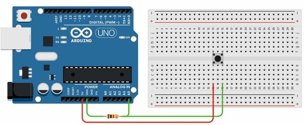
Рис.8.2. Подключение кнопки
Напишем код программы, связанной INPUT_PULLUP (листинг 8.5).
Листинг 8.5. Подтягиюващий резистор. INPUT_PULLUP
void setup(){ Serial.begin(9600);
pinMode(A5, INPUT_PULLUP);
}
void loop(){
boolean button = !digitalRead(A5); Serial.print("button= "); Serial.println(button); delay(30);
}
When the INPUT_PULLUP mode is connected, an internal pull-up resistor with the specified A5 port and a voltage of 5V in one connection is activated. In this case, the message 1 is displayed through the monitor port, which means that the analog port reads the voltage coming from 5V inside the Arduino Uno board. According to the diagram shown in Figure 8.2, when the button is pressed, the circuit is closed and the value 0 will be displayed in the output message on the monitor. We can invert the resulting value 0 to 1 using an exclamation mark (!). In our case, this
!digitalRead(A5). Thus, when the button is pressed, we get a message with a value of 1 and when the button is released, we get 0.
8.3. Distance sensor
Ultrasonic Distance Sensor – The HC-SR04 module uses acoustic radiation to determine the distance to an object. This non-contact sensor ensures high accuracy and stability of measurements. The measurement range is from 2 cm to 400 cm. The sensor readings are practically unaffected by solar radiation and electromagnetic noise. The general view of the HC-SR04 sensor is shown in Figure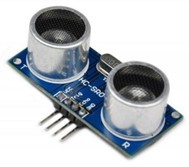
3. HC-SR04 Distance Sensor
HC-SR04 specifications:
1. The measured range is from 2 to 500 cm;
2. accuracy – 0.3 cm;
3. Viewing angle < 15°;
4. The supply voltage is 5 V.
The sensor has 4 outputs:
1. VCC – +5V power supply;
2. Trig(T) – input signal output;
3. Echo (R) – output signal output;
4. GND is the earth.
8.1. The principle of operation of HC-SR04:
1. we apply a pulse of 10 microseconds to the Trig output;
2. Inside the rangefinder, the input pulse is converted into pulses with a frequency of 40 kHz and sent forward through the emitter T;
3. Upon reaching the obstacle, the sent pulses are reflected and received by the receiver R, as a result, we receive an output signal on the Echo pin;
4. directly on the controller side, we convert the received signal into distance according to the formula, depending on which units of measurement we want to get the distance.PulseIn()The function is used to read the pulse length of a signal of a given level at a given contact. If the level is set to HIGH (logical unit), the function will wait for this level to appear on the back, then turn on the timer and stop it when a logical zero (LOW) is formed on the contact again.
Синтаксис
pulseIn(pin, value)
pulseIn(pin, value, timeout)
pin: The number of the input/output port where the signal will be expected. value: The type of expected signal is HIGH or LOW.
timeout: The time to wait for the signal in microseconds. One second is set by default.Questions for self-control
1. What role does INPUT_PULLUP play?
2. What is the distance sensor used for?
3. Describe the principle of operation of the distance sensor?
-